RelaiXed2 -- DIY balanced pre-amplifier

Introduction
The Relaixed2 is an audio pre-amplifier design, created for easy re-builing by DIY audio enthousiasts.
Although inspired by the original RelaiXed design, it has been thoroughly updated in almost all aspects.
It targets the high-end audio segment, and is characterized by:
- The design provides a balanced (XLR) stereo output, and 6 selectable inputs
of which 2 (or 3) are balanced inputs and 4 (or 3) are single-ended (cinch) inputs.
Balanced cabling towards the power amplifier in principle provides cleaner audio signal transfer.
-
Audio volume control and stereo balance control is implemented through a series of relays, 6 per channel,
providing 64 volume steps of 1dB with high quality and reliability,
beyond what can be obtained with other types of volume controllers.
-
Besides through a single front knob, the pre-amplifier can be remotely controlled through IR signals.
It supports multiple IR protocols, to provide large freedom in remote controller selection.
-
The hardware design entails a larger PCB containing the audio processing, the power supplies, some digital decoding,
and the on-board XLR connectors, and is to be placed against the back-plate of the pre-amplifier chassis.
Next to that, a small front-PCB contains the microcontroller, a 2-digit LED display, and the IR receiver,
and is to be located against the front-plate of the pre-amplifier.
-
The software ('firmware') of the embedded microcontroller can be easily updated through a USB connector.
All embedded software as well as the PC interface software is made public available.
-
Upon request I provide the PCBs to other audio hobbyists, as well as the required pre-programmed microcontroller.
These PCBs are being made with first-grade industrial quality, two-layer through-hole, and gold finishing.
For all other components I provide a component table with order-numbers for a well-known internet shop.
Note that I will not freely provide the PCB design files.
-
The relay-based attenuator in this RelaiXed (and in the new passive attenuator) differ from my older designs,
and most designs offered elsewhere, in improvements to avoid audible signal spikes in the audio signal due to relay switches.
These improvements are in: special milli-second based timing of the relay state transitions, avoiding steep voltage transients on the relay coils,
and ground shielding in the PCB layout.
November 2016:The PCBs of this RelaiXed version with classic through-hole
components and the pre-programmed microcontrollers are out of stock.
Unfortunately, I cannot actively support this project anymore due to lack of time.
Note that there are two related alternative designs, documented on their own web pages:
- A little sister with almost the same design, but a more compact implementation
based on SMD components.
-
A passive attenuator,
handling plain (single-ended, cinch) audio. This will finally replace my original attenuator on which I have received so many messages.
The original drive to create the RelaiXed was to provide a high-quality DIY pre-amplifier with balanced inputs/outputs,
for which there were very few choices available. The RelaiXed combines with several available power amplifiers that benefit from
balanced signals, such as the DIY PassLabs mosfet amplifiers
such as this Aleph-X,
the Hypex amplifier modules
such as their UcD400HG,
and Holtom precision amplifiers
such as their HPA_nxV300 R2.
Design information
The design is documented with an extensive set of on-line documents and fotos:
-
The hardware design files with schematics and PCB layout with sizes:
design_20120128.pdf.
-
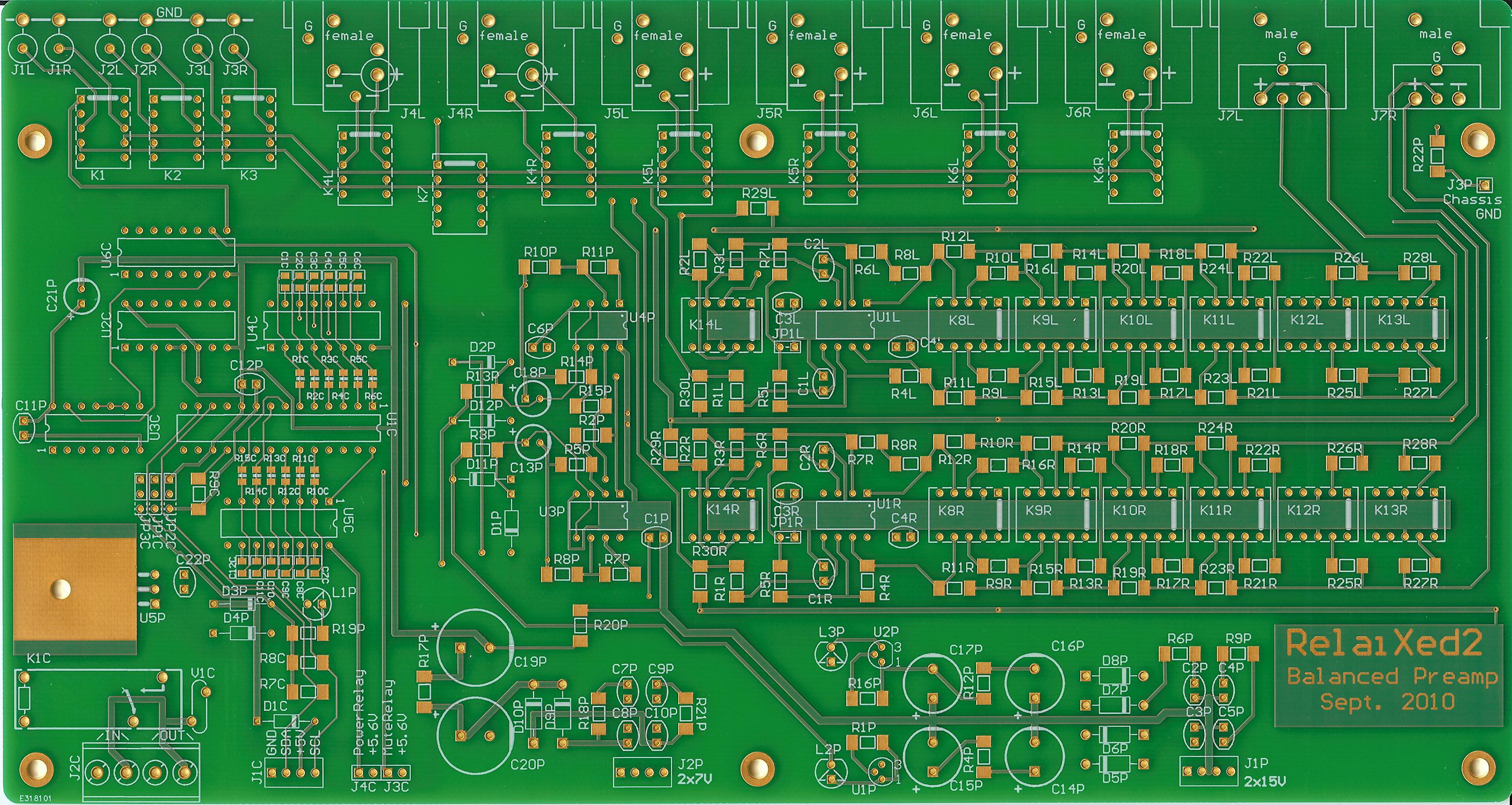
Pictures of the produced PCBs, taken by my flatbed scanner:
Relay-PCB top view
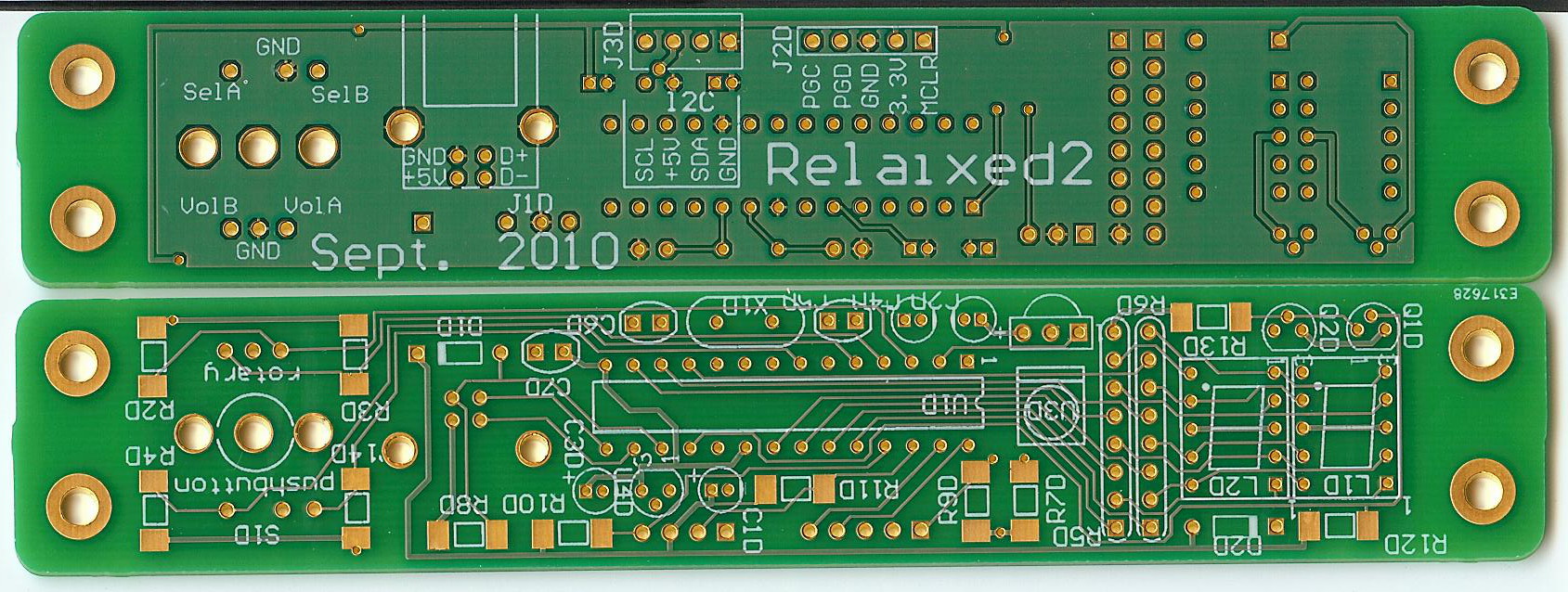
Front-PCB, display and inside view
-
First fotos from the boards with mounted components:
Front-PCB
Relay-PCB
-
The User Manual 2016-09-12,
with basic performance measurements, build instructions and fotos, and operating guide.
-
The HW Design Manual,
with motivation and explanation on the schematcs, and more detailled measurements,
indented to be readable for persons with some electronics background.
-
Component list and prices: New:
Online list of all on-PCB components at Octopart.
The Octopart list allows you to create a Mouser shopping-cart with a single click.
You might also have a look at this somewhat older
Component table
which contains some hints for some extra off-PCB components.
-
A zip file with datasheets of all electronic components used in the design.
-
A SW Design manual explaining the organization of and build process for the embedded software
as well as for the PC-side interface software.
-
The online software project,
that provides all source code in a revision control system (svn),
also in a web-browsable format.
If you want to contribute to improving/extending this software, please contact me.
You might want to check some performance characteristics, which are listed in the
page on the SMD version.
This shows among others a distortion measurement.
For some of my early customers, a new firmware release is available for download from the sourceforge site.
See the user manual on how to install this release in your own Relaixed2 (standard board or SMD version):
-
It fixes an old bug that caused the IR reception to block sometimes after a power-up.
-
It makes the Relaixed to power-up from standby at a 'press' of the knob, instead of at its release.
-
It uses an audio mute during a fraction of a second when switching from input channel.
This helps prevent a strong 'tick' when switching inputs at high volume.
PCB and microcontroller availability
Upon request (by email) I can send PCBs and preprogrammed microcontrollers.
A pair of PCBs costs €72,=.
The preprogrammed PIC18F24J50-I/P microcontroller costs €8,=.
Packaging and mailing with a sign-on-receipt delivery service costs €13,= throughout Europe, and €18,= elsewhere.
Additionally, there is some support for creating a RelaiXed cabinet.
Design background
Obviously, this single page is not suited to explain all of the design background.
Nevertheless I would like to mention some of my ideas that guided this design.
In the past I did design and listening tests on vacuum tube amplifiers.
That background and experience did lead me to:
- Do not use more semiconductors in the audio path then needed.
More semiconductors easily make the sound less open and transparent.
-
For those semiconductors that remain, use quality types that are designed for high bandwidth.
I suspect the non-linear (parasitic) capacitances inside the semiconductors. In devices that
support high-frequency operation these capacitances have lower (less disturbing) values.
Otherwise, the nonlinearity of these capacitances can be reduced by operating the design
at relatively high supply voltages.
-
Always choose good quality components!
Nevertheless, I often find the advertised/dedicated 'high end audio' components over-priced,
and instead look for first-grade professional (industrial) types.
In general it is good to look for low-noise components. Low noise often correlates with good production quality.
The resistor type and brand in this design is chosen for its excellent noise specification of 0.01uV/Volt,
at a very afforable price (compared 'high end audio' resistors).
-
The relais + resistor attenuator avoids the weak contacts of a sliding potentio-meter,
and avoids the single-chip digital controlled integrated attenuators (as I distrust most semiconductors).
Some theory on the operation of the switched attenuator got described in a
wikipedia page.
-
The on-board XLR connectors provide a short and good-quality connection to the audio electronics,
without you having to worry about wiring audio inside your chassis.
No audio signals are routed to the front (display) module.
The digital electronics on the main (relay-) PCB are 'silent' during normal use: the digital signals do not
switch state, there is not a 'life' clock signal. This prevents interference from the digital side into
your precious analog audio signals. Only during volume- or channel-changes there is a moment of digital activity.
The digital circuit is strongly separated from the audio, there is not even a common ground signal.
-
Good-quality components and tools lead to more satisfaction in this nice hobby
and to reliable devices with a long lifetime expectation. There is already too much rubbish being made...
One warning: when turning the volume, one can clearly hear the mechanical clicking sound of the relays. If that would really
disturb you, relay-based attenuators are not your thing...
Recent extensions
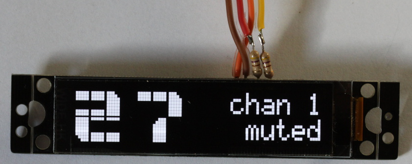
New:Support was added for a 16x2 character OLED display,
as alternative for the standard 2-digit 7-segment display.
This particular
display from ebay
was selected. Obviously, such OLED displays have a great contrast.
Its i2c interface is simply connected in parallel on the 4-wire communication bus between the front- and the main- (relay) PCB.
To use this display, you would need to update the firmware inside the PIC microcontroller to -at least- the 20160910 revision, which can be downloaded from the project sourceforge site.
This display has some issues in obtaining a reliable communication. See how to handle that in the
User Manual.
Thanks for your interest,
Jos van Eijndhoven
Please note that although I (aim to) create professional-quality audio devices, these developments are just hobby for me,
next to a very busy job. These web pages result in many emails to me, which I cannot always answer quickly.
So, please, have some patience with me. I always try to answer within a week, otherwise feel free to ask again!
Dec. 04, 2016